DESCRIPTION
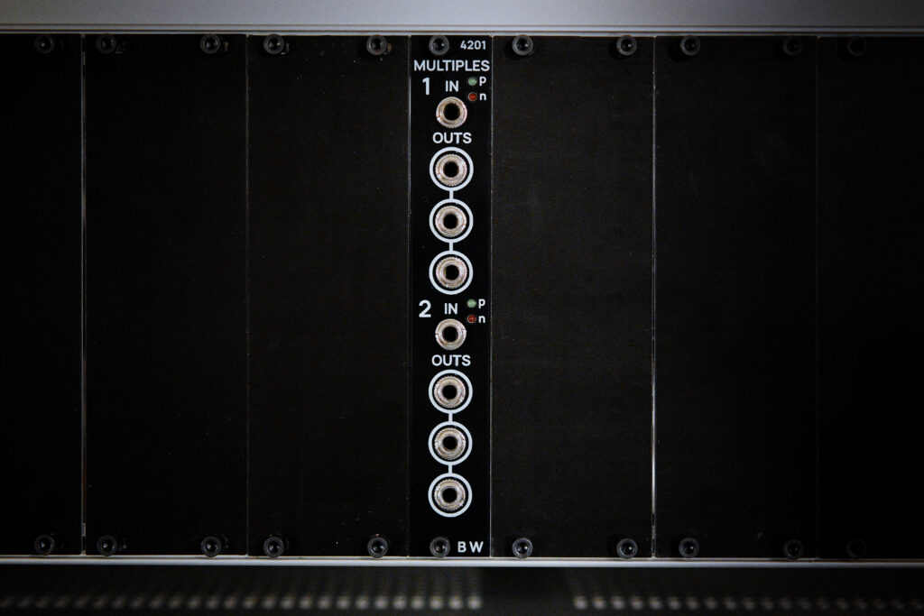
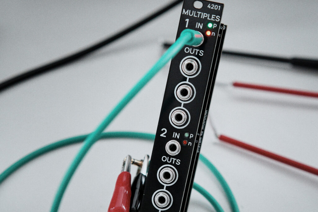
The 4201 module contains two buffered 1:3 multiples. It works with both audio and CV, draws minimal current and uses only readily available, run-of-the-mill components. Special LED indicator lights give visual feedback about polarity and intensity of any signal going through the module and serve as a simple oscilloscope.
This is an open hardware project. Find all design files in the project project repository.
Special thanks to PCBWay for supporting the development of this module by suppplying circuit boards for the prototypes.
OVERVIEW
SIZE
Panel
4HP
Depth
4.5 cm (not including power cable)
POWER
Connector
10-pin
Current draw
3mA @ +12V
3mA @ -12V
THE ELECTRONICS
OP-AMP BUFFERS
Regular op-amp buffers are used to split the input signal. To prevent a high-impedance state (undefined state) on the op-amp inputs, a resistor to ground was added. This way the input to the opamps, and thus the output, is always pulled to 0 V when no cable is connected. For reasons of stability, a resistor in series with the output limits any time constant arising from a possibly connected, capacitive load, e.g., a long patch cable. Think of a long cable as a small capacitor directly connecting the output to ground. When the capacitor is not charged, the output sees it as a short circuit to ground, which makes the op-amp drive as much current as it possibly can to charge up the cap, giving it a tendency to overshoot and oscillate. With some slower op-amp ICs this isn’t as much of a problem. We can better stability by increasing the ouptut resistor, but at the cost of (possibly) slightly detuning any voltage going through the module. This of course depends on the input impedance of the following module, but the eurorack standard only states a low 100 kOhm.
INTEGRATED CIRCUITS
Pretty much any quad opereational amplifier should work with the circuit. I chose LM324, which is one of the very standard op-amps. It is slightly noisy and suffers from a bit of crossover distortion, but does the trick quite well (call it vintage vibe). Other operational amplifiers often used in audio and synthesizer applications like TL074, NE5534 etc. have an unecessarily high slew rate and show a tendency for more instability when processing square waves or other signals with sharp transients. A more high-quality replacement would be OPA4171, but that is harder to come by at the time being. All in all the choice of op-amp is not super critical here.
LED INDICATORS
CIRCUIT BOARDS
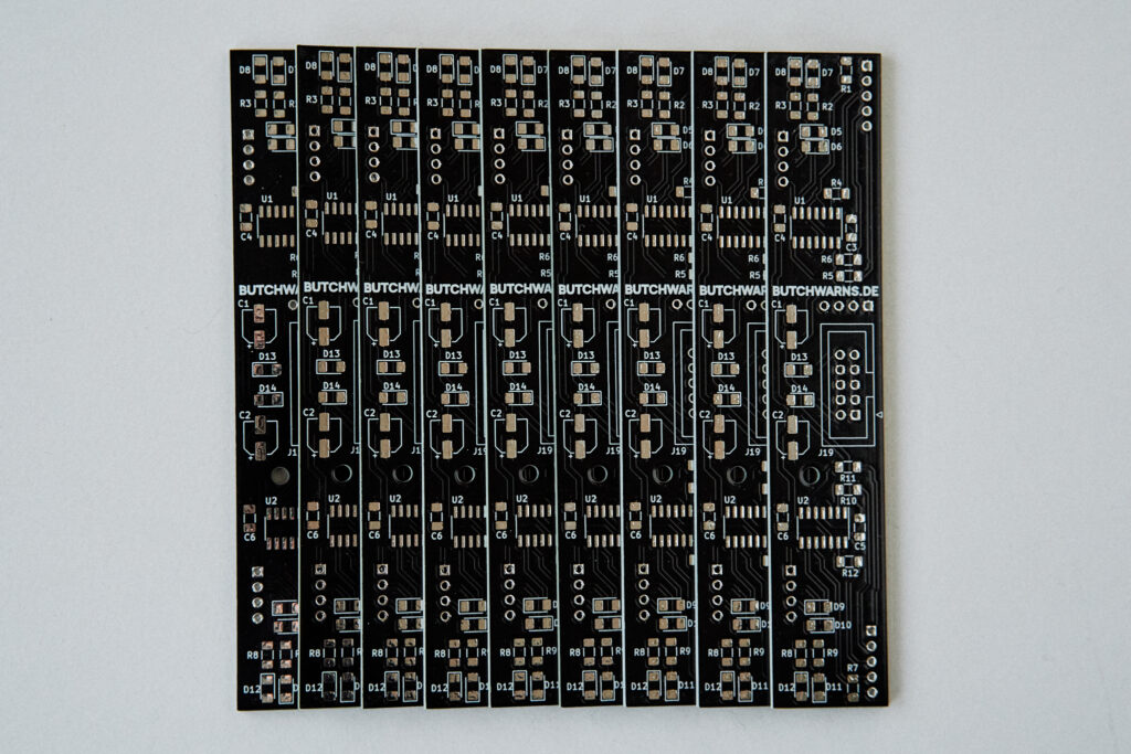
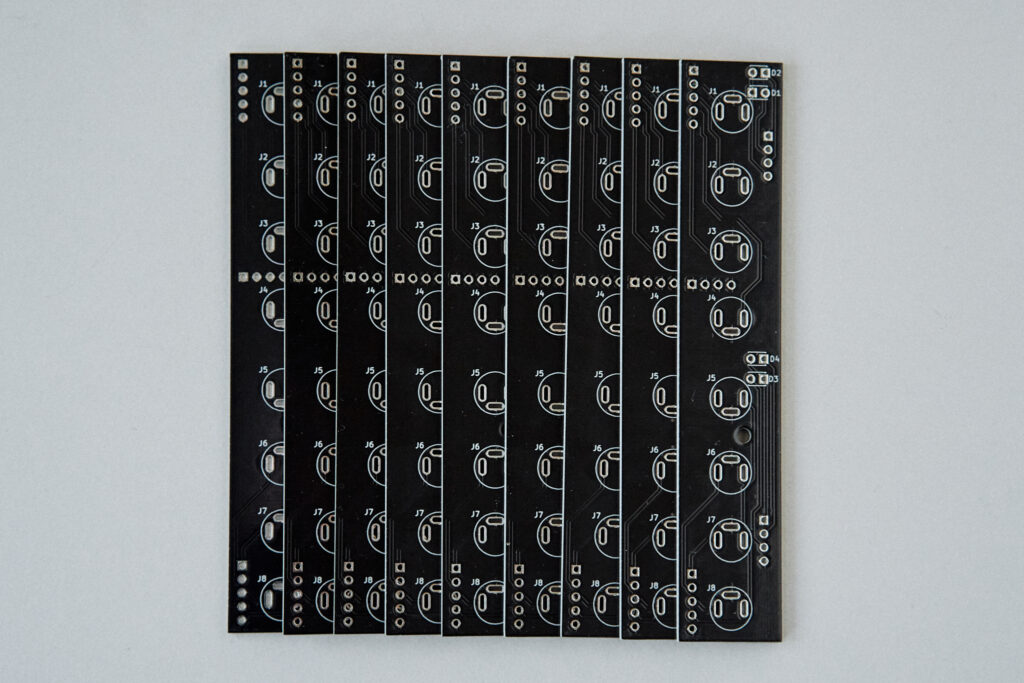
The boards were designed in KiCad. All design files are openly available on GitHub in the project repository.
I also uploaded gerber files so you can order your own boards directly from a manufacturer.
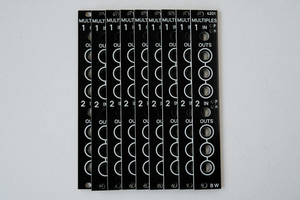
PCBWay.com kindly supplied me with the circuit boards used in the prototypes. All modules came out looking great and I can only recommend using their services!
All components are chosen for availability and precise values are not super critical. 1206 and SOIC packages allow for easy hand soldering, even if you are just starting out with SMT (just get thin solder and watch a quick tutorial). It is of course also entirely possible to have PCBWay assemble all surface mount parts for you, in case you feel like that’s a better option.
